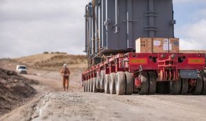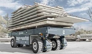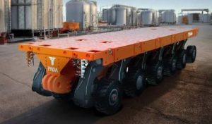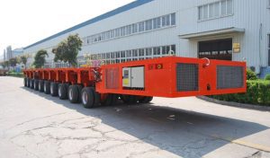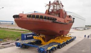
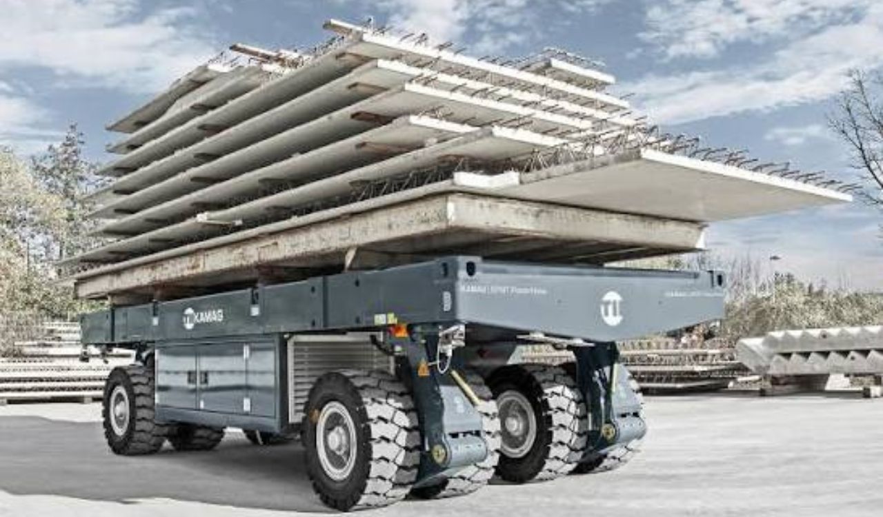
Moving an exceptionally heavy or oversized load with a Self-Propelled Modular Transporter (SPMT) requires more than selecting a transporter with sufficient capacity. The route itself must be evaluated as part of the engineering plan.
An SPMT transport route survey examines whether the complete transporter-and-cargo combination can travel through the proposed route while maintaining suitable clearances, load distribution, ground support, maneuverability, and operational control. A route that appears suitable for conventional trucks may contain a bridge, culvert, narrow turn, weak pavement, utility line, or slope that makes it unsuitable for an SPMT movement.
For engineers, contractors, manufacturers, and heavy transport operators, the objective is not simply to find a route that the SPMT can physically enter. The objective is to establish whether the entire movement can be executed within the technical limits of the equipment, cargo, infrastructure, and project procedure.
What Is an SPMT Transport Route Survey?
An SPMT transport route survey is a systematic inspection and engineering assessment of the path that an SPMT and its cargo will follow. The survey combines physical measurements, infrastructure information, cargo data, transporter configuration, and route analysis to determine whether the proposed movement is feasible. Similar route-planning principles may also apply when assessing other heavy-haul equipment, such as a girder trailer, particularly when transporting large bridge beams or structural components through restricted routes.
Depending on the project, the survey may cover:
- Public roads
- Private access roads
- Industrial facilities
- Construction sites
- Ports and quaysides
- Fabrication yards
- Shipyards
- Plant roads
- Temporary access routes
- Loading and unloading areas
- Final positioning locations
For short industrial movements, the assessment may be concentrated within a site. For complex heavy-haul projects, it can extend over a much longer route and involve multiple infrastructure owners and authorities.
Industry guidance emphasizes that route surveys should be documented and should address obstacles, gradients, cross slopes, ground-bearing pressures, axle-load restrictions, and other route-specific conditions.
Why Is an SPMT Route Survey Important?
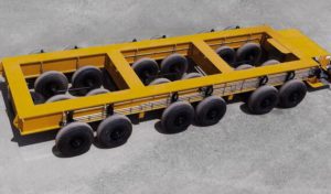
SPMTs can be configured with multiple axle lines and connected longitudinally or laterally to create a platform suitable for different cargo dimensions and weights. This flexibility means that the physical footprint and maneuvering requirements can change significantly from one project to another. By comparison, a semi-truck tractor without a trailer can typically travel at highway speeds of around 90–105 km/h (55–65 mph), although the actual legal and safe speed depends on the vehicle, road, and local regulations.
A route survey helps engineers identify constraints before the equipment and cargo reach a difficult section.
Without adequate route information, problems may only become apparent when the transporter is already committed to the route.
Typical issues include:
- Insufficient road width
- Inadequate turning space
- Low overhead clearance
- Weak pavement or soil
- Restricted bridge capacity
- Buried utilities
- Low-hanging cables
- Excessive gradients
- High cross slopes
- Drainage structures
- Narrow gates
- Temporary construction obstacles
- Inadequate final positioning space
Early identification allows the project team to consider route changes, temporary works, equipment configuration changes, or additional engineering assessments before the movement begins.
What Information Should Engineers Collect Before the Survey?
A route cannot be assessed accurately without knowing what will actually travel along it.
Before the physical survey, engineers should establish the basic cargo and transporter parameters.
Cargo Information
Important cargo data includes:
- Gross weight
- Overall length
- Overall width
- Overall height
- Center of gravity
- Support points
- Load-bearing locations
- Overhang
- Transport orientation
- Sensitivity to inclination or vibration
The cargo dimensions should include temporary transport frames, saddles, beams, lifting arrangements, or other structures that remain part of the transport envelope.
SPMT Configuration
The survey should also account for the planned transporter configuration.
Relevant information can include:
- Number of axle lines
- Module arrangement
- Platform width and length
- Deck height
- Hydraulic suspension characteristics
- Steering capability
- PPU arrangement
- Expected axle reactions
- Required steering modes
An SPMT’s modular design means that the route should be assessed against the actual planned configuration, rather than a generic SPMT specification.
SPMT Route Survey Checklist for Engineers
A useful engineering survey should document more than road width.
| Survey Area | What Engineers Should Check |
| Cargo | Weight, dimensions, center of gravity and support points |
| Transporter | Axle lines, dimensions, deck height and configuration |
| Road width | Minimum usable width and restrictions |
| Turning areas | Swept path, corner clearance and maneuvering space |
| Ground | Bearing capacity, pavement condition and weak areas |
| Bridges | Structural capacity, geometry and restrictions |
| Overhead clearance | Bridges, cables, pipe racks and structures |
| Underground services | Pipes, culverts, tunnels and buried utilities |
| Slopes | Longitudinal gradient and cross slope |
| Obstacles | Poles, barriers, signs, trees, machinery and buildings |
| Drainage | Channels, culverts and drainage crossings |
| Traffic | Road closures, traffic control and public access |
| Destination | Positioning area and installation access |
The exact survey requirements depend on the project, route, equipment, cargo, and applicable engineering procedures.
1. Check the Complete Transport Envelope
One of the first engineering tasks is to define the complete transport envelope.
This means considering not only the cargo but everything that occupies space while the SPMT is moving.
The envelope may include:
- SPMT platform
- Cargo
- Support beams
- Transport frames
- Saddles
- Temporary structures
- Cargo overhang
- Maximum deck height
- Required clearance during steering
For example, a load may have a moderate width while its support arrangement creates a wider overall transport configuration.
Similarly, the highest point of the cargo may not be the only vertical concern. The complete support and transporter arrangement must be considered.
2. Measure Road Width and Lateral Clearance
Available road width should be measured at normal sections and at known restrictions.
Engineers should inspect:
- Straight road sections
- Bridge approaches
- Narrow lanes
- Gate openings
- Factory entrances
- Road shoulders
- Curbs
- Guardrails
- Traffic islands
- Construction barriers
- Drainage channels
The usable width can be considerably smaller than the nominal road width.
For an SPMT movement, engineers also need to consider the lateral space required by the cargo and transporter during steering.
3. Perform a Swept Path Analysis
A stationary transporter footprint does not describe the space required during a turn.
When an SPMT changes direction, different parts of the transporter and cargo follow different paths. The cargo may also extend beyond the SPMT modules.
A swept path analysis helps determine whether the complete configuration can negotiate:
- Intersections
- Roundabouts
- Factory entrances
- Tight corners
- Loading areas
- Plant roads
- Restricted access points
Where fixed objects appear close to the intended path, industry guidance recommends considering a swept-path analysis or, where appropriate, a test movement with a representative load.
What Should a Swept Path Analysis Show?
The analysis should consider:
- Inner clearance
- Outer clearance
- Cargo overhang
- Transporter width
- Steering mode
- Approach direction
- Exit direction
- Nearby fixed objects
This is particularly important because SPMTs can use advanced steering arrangements, but maneuverability does not remove the need to verify the actual path.
4. Check Vertical Clearance
Vertical clearance is another major route constraint.
Potential obstructions include:
- Bridges
- Overpasses
- Power lines
- Communication cables
- Pipe racks
- Gantries
- Building entrances
- Lighting structures
- Road signs
- Industrial equipment
Engineers should determine the minimum available clearance at every critical location.
A simplified transport-height assessment can be represented as:
Transport height = SPMT deck height + support structure + cargo height
However, the actual engineering assessment should also consider the selected configuration, suspension position, route elevation, cargo geometry, and applicable safety clearance requirements.
Hydraulic suspension may allow controlled adjustment of deck height on suitable equipment, but it should not be treated as a substitute for proper clearance verification.
5. Assess Bridges and Culverts
A bridge crossing requires more than checking whether the SPMT physically fits underneath it.
Engineers may need information about:
- Structural capacity
- Permitted axle loads
- Deck condition
- Bridge geometry
- Load distribution
- SPMT axle arrangement
- Approach conditions
- Existing restrictions
Culverts and buried structures also deserve attention.
A road may appear structurally adequate while a localized underground structure has a lower permissible loading capacity.
Industry SPMT guidance specifically highlights the need to consider bridges, bridge-like structures, pipelines, and culverts when assessing ground-bearing conditions.
Why Axle Load Matters
The total cargo weight alone does not determine the effect on infrastructure.
The engineering team should understand how the combined transporter and cargo loads are distributed across the SPMT axle lines and how those reactions interact with the supporting structure.
This becomes particularly important when crossing bridges, culverts, temporary roads, or areas with known load restrictions.
6. Evaluate Ground-Bearing Capacity
Ground-bearing capacity is one of the most important technical considerations in an SPMT route survey.
The supporting surface may consist of:
- Asphalt
- Concrete
- Compacted soil
- Gravel
- Temporary road construction
- Steel plates
- Timber mats
- Reinforced slabs
The survey should identify areas where the surface may not safely support the expected loading.
Potential weak zones include:
- Soft soil
- Road shoulders
- Recently excavated areas
- Poorly compacted fill
- Damaged pavement
- Drainage crossings
- Underground structures
- Construction zones
- Temporary access roads
Where required, engineers may investigate ground improvement or load-distribution measures.
The appropriate solution depends on the actual ground conditions and calculated loading; simply adding plates or mats should not be treated as an automatic solution without engineering verification.
7. Measure Gradients and Cross Slopes
The route survey should record both longitudinal gradients and transverse slopes.
Longitudinal Gradient
A longitudinal gradient is the rise or fall along the direction of travel.
Engineers should identify:
- Uphill sections
- Downhill sections
- Ramp transitions
- Loading ramps
- Dock approaches
- Sudden elevation changes
Gradient can affect traction, load distribution, steering, braking, and transporter operation.
Cross Slope or Camber
Cross slope is the difference in elevation across the travel surface.
It can influence the lateral loading of the SPMT and cargo.
The acceptable operating condition depends on factors such as:
- SPMT configuration
- Cargo center of gravity
- Hydraulic suspension
- Ground condition
- Transport procedure
- Manufacturer limits
- Project engineering requirements
A hydraulic suspension system can accommodate controlled surface variations, but it does not make an unsuitable slope or weak surface acceptable.
8. Identify Overhead and Underground Utilities
Utilities can become critical route constraints, especially on industrial and urban routes.
Overhead Utilities
Survey teams should identify:
- Power lines
- Telecommunications cables
- Lighting systems
- Pipe bridges
- Industrial pipe racks
- Gantries
- Sign structures
Locations and available clearance should be documented rather than estimated visually.
Underground Utilities
The survey should also investigate:
- Water pipelines
- Gas lines
- Electrical cables
- Drainage systems
- Sewers
- Culverts
- Tunnels
- Buried process infrastructure
This is particularly important where the SPMT will travel through industrial facilities or over areas with incomplete historical site information.
9. Inspect Road Surface and Drainage
Surface condition can influence transporter movement and load behavior.
Engineers should document:
- Potholes
- Cracks
- Rutting
- Settlement
- Uneven transitions
- Loose aggregate
- Damaged concrete
- Standing water
- Poor drainage
Drainage channels should also be inspected because they can create localized weaknesses or abrupt changes in elevation.
A route that appears suitable during dry conditions may require reassessment after significant rainfall or other environmental changes.
10. Examine Traffic and Operational Constraints
A technically suitable route can still require operational controls.
The survey should identify:
- Traffic volume
- Intersections
- Traffic signals
- Road closures
- Restricted access
- Pedestrian areas
- Public-road interfaces
- Construction activities
- Security gates
- Shift-change traffic
- Emergency access requirements
For industrial projects, coordination with the site operator may be necessary to temporarily relocate equipment, stop vehicle movements, or control access during the SPMT operation.
11. Assess Loading, Unloading, and Final Positioning Areas
Route planning should not end at the destination gate.
Engineers should inspect the complete movement from the loading location to the final position.
The destination assessment may include:
- Approach route
- Turning area
- Final positioning space
- Ground capacity
- Installation clearance
- Crane interface
- Jacking areas
- Temporary support locations
- Required steering movements
This is particularly important when the SPMT is being used to position bridge sections, industrial modules, vessels, transformers, or other equipment with tight installation tolerances.
Route Survey Data Engineers Should Document
A route survey should produce usable engineering information rather than only photographs.
| Data | Example Information |
| Route location | GPS/site reference and chainage |
| Road width | Minimum usable width |
| Clearance | Minimum vertical and lateral clearance |
| Gradient | Maximum uphill/downhill section |
| Cross slope | Critical transverse inclination |
| Ground | Surface condition and bearing information |
| Structures | Bridges, culverts and underground structures |
| Utilities | Overhead and buried services |
| Obstacles | Fixed and temporary restrictions |
| Turns | Swept-path requirements |
| Traffic | Access and control requirements |
| Destination | Final positioning and installation area |
Photographs, drawings, site plans, measurements, survey coordinates, utility records, and engineering calculations can then be combined into the project transport plan.
How Engineers Decide Whether a Route Is Feasible
The survey does not simply produce a list of obstacles. Engineers must compare the collected information with the proposed transport configuration.
A typical evaluation process is:
Step 1: Establish Cargo Parameters
Confirm weight, dimensions, center of gravity, support points, and transport orientation.
Step 2: Select a Preliminary SPMT Configuration
Determine the approximate axle-line arrangement, platform dimensions, deck height, and required steering capability.
Step 3: Map the Route
Document the complete route from loading point to final position.
Step 4: Identify Critical Sections
Mark bridges, tight turns, narrow sections, low clearances, steep grades, weak ground, utilities, and other constraints.
Step 5: Analyze the Transport Envelope
Compare the cargo and SPMT dimensions against available horizontal and vertical clearances.
Step 6: Assess Infrastructure Loading
Review expected axle reactions and compare them with the capacity of bridges, pavements, culverts, and other supporting structures.
Step 7: Determine Required Modifications
Potential measures may include:
- Temporary road strengthening
- Obstacle removal
- Utility protection
- Traffic controls
- Route widening
- Alternative access
- Ground improvement
- Temporary ramps
Step 8: Confirm the Final Route
The final route should be reviewed against the actual SPMT configuration and project conditions before movement.
SPMT Route Survey vs Conventional Heavy-Haul Survey
Many principles overlap with conventional heavy-haul planning, but SPMT movements can involve different maneuvering and positioning requirements.
| Factor | SPMT Route Survey | Conventional Heavy-Haul Survey |
| Road width | Critical | Critical |
| Ground capacity | Critical | Critical |
| Bridge assessment | Critical | Critical |
| Overhead clearance | Critical | Critical |
| Swept path | Highly important | Highly important |
| Steering modes | Multiple configurations possible | Depends on trailer system |
| Lateral movement | Possible with suitable SPMT | Equipment-dependent |
| Final positioning | Often part of the movement | May require separate equipment |
| Industrial-site movement | Common | Application-dependent |
| Self-propelled movement | Yes | Usually no |
The key point is that route suitability should be determined from the actual cargo and equipment combination, not from a generic comparison between transport equipment types.
Where SPMT Route Surveys Are Commonly Used
Industrial Plants
Refineries, petrochemical facilities, power plants, and manufacturing sites may contain pipe racks, process equipment, narrow access roads, and complex underground infrastructure.
Ports and Quaysides
Heavy modules may need to move between vessels, quays, storage areas, and fabrication facilities. Ground capacity, ramps, quay structures, and final positioning areas become important.
Bridge and Infrastructure Projects
SPMTs can transport bridge sections and other large structural components where precise positioning and controlled movement are required.
Shipyards
Large ship sections and marine structures may need controlled movement through fabrication and assembly areas.
Construction Sites
Construction projects may require movement of large structural elements, transformers, machinery, and prefabricated assemblies through temporary or restricted routes.
What About Multiwheelers, Modultrailers, and Port Trailers?
Not every heavy cargo movement requires an SPMT.
A multiwheeler can be appropriate for certain heavy road transportation applications where a suitable prime mover and road route are available.
A modultrailer or conventional modular trailer can similarly provide a modular axle arrangement for heavy-haul operations while relying on a tractor or prime mover.
Port trailers are generally designed for specific port and terminal logistics applications and are not equivalent to an SPMT for exceptionally heavy, irregularly shaped project cargo.
The choice should be based on:
- Cargo weight
- Cargo dimensions
- Route geometry
- Required steering
- Ground conditions
- Transport distance
- Final positioning requirements
- Infrastructure limitations
- Project schedule
Equipment cost alone should not determine the transport method.
Similarly, semi trailer leasing prices are relevant when comparing conventional trailer logistics, but an SPMT project requires consideration of engineering, configuration, route preparation, operation, and positioning requirements in addition to equipment cost.
How Shiyun Trailers’ SPMT Systems Fit Into Route Planning
SPMT configuration and route engineering are closely connected because the transporter can be assembled in different axle arrangements and controlled through integrated steering and hydraulic systems.
Shiyun Trailers’ SPMT product information describes a modular system using axle modules and a Power Pack Unit, allowing the platform configuration to be adapted to different cargo requirements.
The route survey should therefore be performed with the intended transporter configuration in mind, including its width, length, deck height, steering requirements, load distribution, and hydraulic operating conditions.
Conclusion
An SPMT transport route survey is an engineering assessment that connects cargo characteristics, transporter configuration, infrastructure, ground conditions, route geometry, and operational requirements. The most important checks include road width, swept path, vertical clearance, bridge and culvert capacity, ground-bearing conditions, gradients, cross slopes, utilities, obstacles, traffic restrictions, and final positioning space.
The survey becomes most useful when engineers evaluate these factors against the actual SPMT configuration and cargo, rather than treating the route as a conventional truck road. For heavy industrial modules, bridge components, plant equipment, port cargo, and other oversized loads, careful route engineering can identify constraints early and provide the information needed for route modification, temporary works, equipment configuration, and controlled execution.
Frequently Asked Questions
What is an SPMT transport route survey?
An SPMT transport route survey is an engineering assessment of the complete route that an SPMT and its cargo will use. It examines dimensions, clearances, ground conditions, structures, utilities, slopes, obstacles, turning areas, and final positioning requirements.
What do engineers check during an SPMT route survey?
Engineers typically check road width, swept paths, overhead clearance, bridges, culverts, ground-bearing capacity, gradients, cross slopes, utilities, drainage, obstacles, traffic restrictions, and destination conditions.
Why is ground-bearing capacity important for SPMT transport?
SPMTs can distribute very large loads across multiple axle lines, but the supporting surface still needs adequate capacity. Weak soil, pavement, shoulders, culverts, or buried structures can create localized loading concerns.
What is a swept path analysis for an SPMT?
A swept path analysis determines the area occupied by the transporter and cargo while moving through a turn. It helps engineers identify potential conflicts with curbs, buildings, barriers, utilities, structures, and other fixed objects.
Does an SPMT route survey include bridge checks?
Yes. Bridges should be assessed for structural capacity, geometry, clearance, axle loading, load distribution, and approach conditions before an SPMT movement is approved across them.
How do SPMT steering systems affect route planning?
SPMT steering systems can provide multiple movement patterns, including controlled turning and lateral or crab movement on suitable equipment. However, the specific steering capability must be considered together with the cargo dimensions, swept path, ground conditions, and route geometry.
Can an SPMT use the same route as a multiwheeler or modultrailer?
Not necessarily. Although some routes may accommodate different heavy transport systems, each movement should be assessed according to the actual equipment dimensions, axle arrangement, load distribution, maneuverability, and operating requirements.