The Self-propelled modular transporters, commonly called SPMTs, have changed how civil engineers move and install extremely heavy structures.
They can carry complete bridge spans, precast concrete sections, steel girders, tunnel elements and other large components. Instead of building every part in its final position, contractors can assemble the structure in a controlled area and move it when the site is ready.
This approach supports faster construction, shorter road closures and safer working conditions. It is especially valuable in busy cities, railway corridors, industrial zones and locations where conventional cranes cannot operate effectively.
SPMT operations still require detailed engineering. Load distribution, structural capacity, ground conditions, route geometry, stability and weather must all be assessed before a move begins.
What Is a Self-Propelled Modular Transporter?
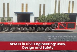
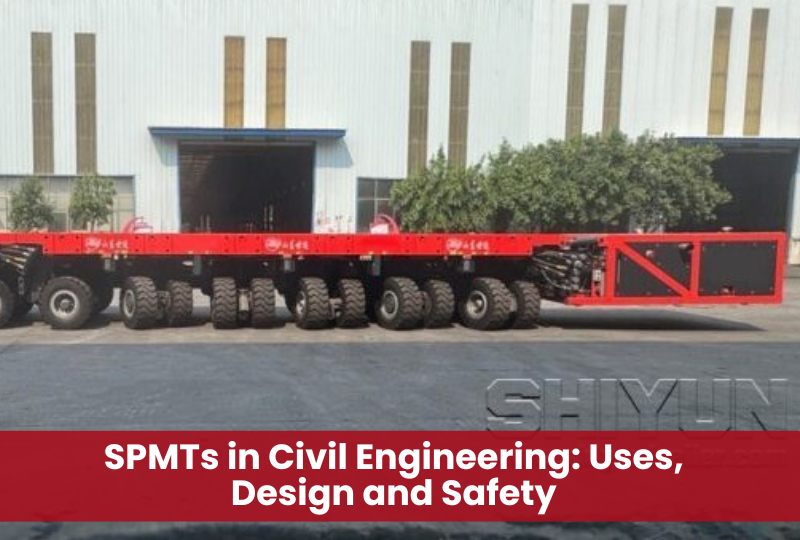
A self-propelled modular transporter is a multi-axle platform designed to lift and move very heavy loads over relatively short distances.
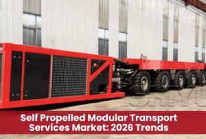
Unlike a conventional modular trailer, an SPMT does not need a tractor unit to pull it. Hydraulic drive units provide propulsion. A Power Pack Unit supplies hydraulic pressure for steering, suspension, braking and movement.
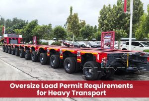
SPMT modules can be connected longitudinally, transversely or in more complex arrangements. This allows engineers to create a transport platform that matches the length, width, weight and centre of gravity of the load.
Commercial SPMT systems may use modules with four, five, six or eight axle lines. Certain configurations can provide capacities of up to approximately 44 tons per axle line. Actual capacity depends on the manufacturer, model, operating conditions and engineering configuration.
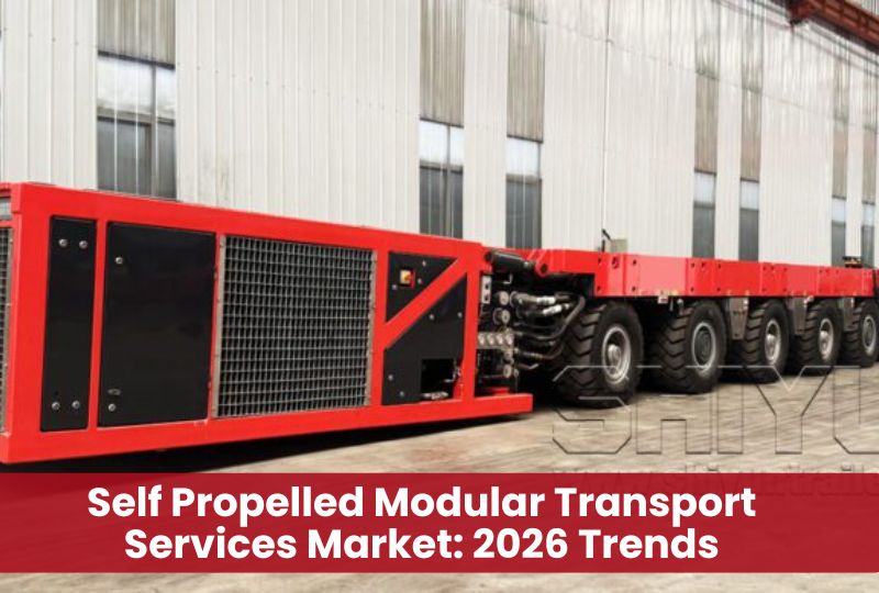
An axle line is a row of wheel assemblies positioned across the transporter. Several axle lines distribute the load across a larger surface area.
SPMTs normally move at a low speed. Their purpose is not long distance road transportation. Their main strength is controlled movement of exceptionally large loads within construction sites, staging areas, ports and infrastructure corridors.
Main Components of an SPMT
An SPMT is made from several mechanical, hydraulic and electronic systems.
1. Transporter modules
The module forms the main load carrying platform.
A typical module contains a strong central spine beam. Wheel assemblies, also known as pendulums, are attached beneath it. Modules are joined with pins, deck bolts and transverse coupling blocks.
Connecting several modules increases the platform size and payload capacity.
2. Axle lines and wheel assemblies
Each axle line contains several wheel sets.
The large number of tyres spreads the load across the ground. This reduces the force applied at a single contact point. However, high wheel loads can still create serious local and deep ground failures if the working platform is not designed correctly.
3. Hydraulic suspension
Hydraulic cylinders connect the wheel assemblies to the transporter structure.
The suspension performs several functions:
- It raises and lowers the transporter deck.
- It helps maintain a controlled platform level.
- It distributes reactions between connected wheel groups.
- It allows the wheels to follow small variations in the ground surface.
A typical hydraulic stroke may be around 600 millimetres, although this varies by equipment model. The available stroke can be reduced by chassis deflection, tyre compression, uneven ground and changes in gradient.
4. Power Pack Unit
The Power Pack Unit is commonly known as the PPU.
It contains the engine, hydraulic pumps, reservoir and control equipment required to operate the transporter. Traditional PPUs use diesel engines. Electric and hybrid power systems are also becoming available.
5. Steering system
SPMT steering is controlled electrohydraulically.
Individual wheel assemblies can be rotated to create several steering patterns. This makes the transporter far more manoeuvrable than a conventional heavy haul trailer.
6. Control system
An operator controls the SPMT through a wired or wireless control unit.
The system can manage:
- Travel direction
- Travel speed
- Steering mode
- Hydraulic suspension height
- Braking
- Emergency shutdown
The operator normally walks near the transporter while maintaining a clear view of the route, load and spotters.
How Does an SPMT Work?
An SPMT uses four main hydraulic functions:
- Suspension
- Drive force
- Brake force
- Steering
These systems work together to move the load while maintaining stability and controlled axle reactions.
Hydraulic load distribution
The wheel assemblies are divided into hydraulic groups.
Oil can move between cylinders within a group. This helps the wheels follow ground variations while supporting the transporter deck.
The arrangement of hydraulic groups creates virtual support points beneath the load. These support points define the transporter’s tipping lines.
A three point hydraulic arrangement is statically determinate and creates a stable support plane. Four point arrangements may be used, but they require closer control because load reactions can become statically indeterminate.
Steering movement
The steering system allows several movement patterns.
Straight steering
The SPMT moves forward or backward along its longitudinal axis.
Crab steering
All wheels point in the same diagonal direction. The transporter can move sideways while maintaining the same platform orientation.
Transverse steering
The transporter moves across its width.
Carousel steering
The wheels follow circular paths around a central point. This allows the entire platform to rotate within a confined area.
Pivot steering
The transporter turns around a selected axle line or defined steering centre.
These steering modes make SPMTs useful where a long trailer cannot complete a conventional turn.
Raising and lowering the load
The hydraulic suspension can lift the deck beneath a structure supported on temporary stools.
The typical process is simple:
- The SPMT enters beneath the load at a low deck height.
- The suspension extends.
- The transporter accepts the load from the temporary supports.
- The SPMT moves the structure.
- The deck lowers at the destination.
- The load transfers onto its permanent or temporary supports.
This self-loading ability can reduce the need for a large crane. It does not remove the need for jacking, gantries or cranes in every project. Additional lifting systems may still be required when the vertical movement exceeds the transporter stroke.
Why SPMTs Are Important in Civil Engineering
Modern infrastructure projects often take place beside active roads, railway lines, buildings and utilities.
Traditional construction can require long closures and extensive work above or beside live traffic. SPMTs allow more work to be completed in a separate staging area.
A bridge span, tunnel section or prefabricated structure can be built away from the final location. It can then be transported and installed during a planned closure.
This method can reduce the amount of work performed in a congested or hazardous area. It can also allow construction and foundation work to progress at the same time.
The Federal Highway Administration identifies shorter traffic disruptions, better work zone safety, improved constructability and greater use of prefabrication as major benefits of SPMT bridge moves.
Major Civil Engineering Applications of SPMTs
Accelerated bridge construction
Bridge installation is one of the best known uses of SPMTs.
In accelerated bridge construction, a complete superstructure can be assembled near the road. The old bridge is removed, and the new structure is transported into place during a short closure.
SPMTs can carry:
- Complete bridge spans
- Steel girder assemblies
- Concrete box girders
- Bridge decks
- Pedestrian bridges
- Railway bridges
- Approach structures
- Temporary bridges
The Federal Highway Administration describes SPMTs as computer controlled platforms that can lift, carry and position large bridge structures. They can move in multiple directions and travel at approximately walking speed.
Bridge deck replacement
SPMTs can remove old deck sections and install new prefabricated panels during the same closure.
The Lewis and Clark Bridge project used SPMTs and a specially designed steel frame to handle full width precast deck panels. New panels were transported to the work area, while removed panels were carried away.
The project replaced 103 prefabricated deck panels. Normal weekday traffic was maintained, and each panel was handled during a controlled night closure.
Bridge girder installation
SPMTs can transport and position individual girders where crane access is restricted.
A transporter may also carry a purpose-built cantilever frame. The frame extends beyond the platform and allows a girder to be positioned over bearings or an excavation.
A Colorado rail bridge project used an engineered cantilever arrangement on SPMTs to install steel girders beneath an interstate. The configuration included transport beams, counterweights and hoisting equipment. Each girder was positioned in about one hour.
Tunnel and underpass construction
Large tunnel sections can be built beside a railway or highway and then transported into place.
SPMTs may also move tunnel boring machine components, launch equipment, formwork and temporary structures. They are often combined with jacking, skidding or gantry systems when heavy equipment must be lowered into a shaft.
Prefabricated construction
Prefabrication allows major structural elements to be produced in controlled conditions.
SPMTs can transport:
- Precast concrete modules
- Structural steel frames
- Roof sections
- Airport structures
- Stadium components
- Station modules
- Large building sections
- Utility and service modules
The structural component must be designed for its temporary transport condition. Supports used during the move may create forces that do not exist in the permanent structure.
Viaduct and railway construction
SPMTs can move railway bridge decks, viaduct segments and preassembled track structures.
Their multidirectional steering is useful where the final alignment is not directly accessible. Transporters can approach from the side, rotate the load and align it with bearings or temporary supports.
Heavy civil maintenance
SPMTs are also used during rehabilitation and decommissioning.
They can remove complete structural sections and carry them to a dismantling area. This can reduce demolition work above active infrastructure.
The Role of SPMTs in Accelerated Bridge Construction
Accelerated bridge construction is a project delivery approach that reduces the time spent working at the final bridge location.
It often combines three elements:
- Prefabricated Bridge Elements and Systems
- Offsite or nearby assembly
- Rapid installation methods
SPMTs connect prefabrication with final installation.
The new bridge can be built while foundations, abutments and other site works are completed. Once both areas are ready, the bridge is transported into position.
This can reduce closure periods from months to days, hours or a weekend. The actual duration depends on demolition requirements, foundation work, alignment, closure planning and the complexity of the move.
Typical SPMT Bridge Move Sequence
A bridge move normally follows a carefully planned sequence.
1. Construct the bridge in a staging area
The bridge is assembled near the final site.
The staging area must have enough space for construction, temporary supports, SPMT access and final departure.
2. Complete temporary support works
Temporary stools, towers or support frames hold the bridge at the required pickup elevation.
The supports must allow the SPMT to enter beneath the structure.
3. Assemble and test the SPMT configuration
Modules are connected to create the required number of axle lines.
Hydraulic groups, steering, brakes and the control system are tested.
4. Position the transporter
The SPMT moves beneath the structure.
Surveyors and spotters verify its position relative to the designed support points.
5. Lift the structure
The hydraulic suspension extends.
The load is gradually transferred from the temporary supports to the transporter. Axle loads, deck elevation and structural movement are monitored.
6. Move the bridge
The transporter follows the approved movement path.
Operators maintain the planned speed, steering geometry and hydraulic settings.
7. Align the bridge
The steering system allows small longitudinal, transverse and rotational corrections.
Survey equipment confirms alignment with bearings, abutments and centre lines.
8. Lower the bridge
The hydraulic suspension retracts.
The bridge is transferred onto bearings or temporary supports.
9. Remove the SPMT
Once the load transfer is confirmed, the transporter leaves the installation area.
Closure joints, connections, barriers and approach works can then be completed.
Engineering Requirements for an SPMT Move
An SPMT move is a temporary works operation. It requires coordination between structural engineers, geotechnical engineers, transport specialists, surveyors, contractors and equipment operators.
Load weight
The engineering team must determine the complete transported weight.
This includes:
- The main structure
- Temporary steelwork
- Support frames
- Saddles and bolsters
- Jacking equipment
- Rigging and restraints
- Counterweights
- Equipment carried on the structure
Estimated weights should be verified as the design develops. Unexpected weight can increase axle reactions and reduce stability margins.
Centre of gravity
The centre of gravity is one of the most important inputs.
Engineers must know:
- Its longitudinal position
- Its transverse position
- Its height above the transporter
- Whether it changes during lifting or movement
A high centre of gravity increases overturning effects during braking, turning and travel over uneven ground.
An eccentric centre of gravity can overload one hydraulic group even when the average axle line load appears acceptable.
SPMT configuration
The number of axle lines is selected from the load, equipment capacity and site conditions.
The configuration may include:
- A single transporter file
- Two files positioned side by side
- Several modules connected head to tail
- Separate transporter trains working electronically together
- Open centre or split arrangements
- Custom widening systems
The arrangement must provide enough capacity, stability, structural strength and manoeuvrability.
Support locations
Loads must enter the SPMT through structurally suitable points.
Support stools, saddles and transport beams should transfer reactions into strong parts of the transporter spine beam.
The structure being transported must also resist the reactions applied at these temporary support locations.
A bridge designed to sit on bearings near its ends may experience different bending and torsional effects when supported by an SPMT arrangement.
Axle line load
A preliminary average axle line load can be calculated as:
Average axle line load = Gross supported transport weight ÷ Number of effective axle lines
Consider an illustrative transport with:
Cargo weight: 800 tonnes
Temporary frames and equipment: 80 tonnes
Transporter self-weight: 160 tonnes
Gross transport weight: 1,040 tonnes
Number of axle lines: 32
The basic average is:
1,040 ÷ 32 = 32.5 tonnes per axle line
This is only an early screening calculation.
Final reactions will be affected by hydraulic grouping, support positions, centre of gravity, chassis deflection, turning, braking, wind, gradient and uneven ground. The allowable axle line load must also be checked against the selected equipment specification.
Hydraulic stability
Hydraulic stability relates to the pressure and reaction within each hydraulic support group.
A transporter may have enough total axle capacity but still overload one hydraulic group.
The analysis must consider:
- Group geometry
- Load eccentricity
- Centre of gravity height
- Platform level
- Hydraulic pressure limits
- Temporary support reactions
- Changes during steering or turning
Geometric stability
Geometric stability is controlled by the relationship between the combined centre of gravity and the tipping lines.
The centre of gravity must remain within the effective support polygon.
Uneven ground, platform tilt and dynamic forces can move the resultant force toward a tipping line. Stability checks must consider both static and moving conditions.
Structural capacity of the transporter
Hydraulic capacity alone is not enough.
Engineers must also check:
- Local deck loading
- Spine beam bending
- Chassis deflection
- Connection forces
- Module coupling loads
- Support beam reactions
- Stress concentrations
The Temporary Works Forum notes that the transporter arrangement is structurally safe only when hydraulic capacity, spine beam stresses, deflection and connection loads have all been checked.
Structural capacity of the cargo
The transported structure must be analysed for temporary load cases.
These may include:
- Pickup from temporary stools
- SPMT support reactions
- Hydraulic levelling differences
- Braking forces
- Turning forces
- Wind loading
- Local support stresses
- Differential movement between transporter groups
Temporary transport forces can control the design of diaphragms, bracing, lifting points or support frames.
Dynamic forces
Even though SPMTs move slowly, dynamic effects still matter.
The main dynamic actions include:
- Acceleration
- Normal braking
- Emergency braking
- Turning
- Surface irregularities
- Wind
- Sudden steering corrections
Turning generates lateral force and an overturning moment. Braking creates longitudinal force. Both effects become more significant as the centre of gravity height increases.
Ground bearing pressure
SPMTs distribute weight through many tyres, but the resulting ground demand can still be substantial.
Two types of ground response should be considered.
Local response
This relates to the pressure beneath individual tyres or wheel groups.
Global response
This relates to the combined loaded footprint of the complete transporter.
A surface may resist the local tyre pressure but still fail through deeper soil layers.
Working platform design
The full travel route should be treated as a working platform.
The design may need to consider:
- Soil strength
- Groundwater
- Fill material
- Compaction
- Pavement thickness
- Buried utilities
- Culverts and drainage structures
- Retaining walls
- Existing bridge decks
- Differential settlement
- Weather sensitivity
- Edge distances
SPMTs create closely spaced wheel loads that can rotate around a vertical axis during steering. A specialist geotechnical assessment should therefore be completed early in the project.
Traction and gradient
Capacity does not guarantee movement.
The transporter must have enough traction and drive force to overcome:
- Road gradient
- Rolling resistance
- Surface contamination
- Initial acceleration resistance
- Tyre deformation
- Weather effects
Wet, dirty or smooth surfaces can reduce both propulsion and braking performance. The worst combination of gradient, rolling resistance and available traction should be assessed.
Route geometry
A detailed route survey should confirm:
- Travel width
- Turning space
- Vertical clearances
- Overhead utilities
- Side clearances
- Road gradients
- Changes in crossfall
- Transition curves
- Surface condition
- Drainage features
- Underground services
- Final escape route for the transporter
Digital terrain models, total stations, laser scanning and LIDAR can support route planning.
Transport frame design
Many structures cannot sit directly on the SPMT deck.
A transport frame may be required to:
- Spread concentrated reactions
- Match the cargo support points
- Increase clearance
- Stabilize the structure
- Provide connection points
- Support jacking systems
- Carry counterweights
- Create a cantilever
The frame should be designed for bending, shear, torsion, local buckling, connection forces and temporary dynamic loads.
SPMT Steering Modes and Their Engineering Value
Steering flexibility is one of the main reasons engineers choose SPMTs.
A conventional trailer follows a turning path. An SPMT can change its movement direction without changing the orientation of the load.
This helps in narrow construction zones.
For example, a bridge span can move forward from its staging area, travel sideways toward the road and rotate above the final supports.
The wheels may provide nearly full rotational movement, although the exact range depends on the equipment. Multiple steering modes allow straight, diagonal, transverse and circular movement.
SPMT Versus Conventional Modular Trailer
SPMTs and conventional modular trailers can both carry heavy loads. Their operating methods are different.
Conventional modular trailer
A conventional modular trailer is normally pulled or pushed by tractor units.
It is suitable for longer transport routes and public road movements. Its turning path depends on the steering geometry of the trailer and prime movers.
Self-propelled modular transporter
An SPMT contains its own drive system.
It offers more precise movement and a wider range of steering modes. It is better suited to slow site movement, final positioning and confined construction areas.
SPMTs are also different from Self-Propelled Transporters, or SPTs. SPMTs generally provide electrohydraulic steering at individual pendulum assemblies. SPTs often use a dedicated drive module and more limited mechanical steering arrangements.
SPMT Versus Crane Installation
A crane lifts a load through the air. An SPMT supports the load from below and carries it along the ground.
A crane may be better when:
- The load must pass over obstacles.
- A large vertical lift is required.
- The transport path is unavailable.
- Suitable crane setup space exists.
An SPMT may be better when:
- The load can be assembled nearby.
- The route can support the transporter.
- Crane access is restricted.
- The load is too large for a practical crane configuration.
- A short installation window is required.
- Precise horizontal movement is important.
Many projects use both systems. A crane or gantry may place the structure onto temporary supports. The SPMT then transports it to the installation point.
SPMT Versus Skidding Systems
Skidding systems move a structure along rails, beams or prepared tracks.
Skidding can be effective when the load follows a simple, fixed path.
SPMTs provide more flexibility because they can steer and change direction. They do not require a continuous skid track.
A skidding system may still be preferable when ground clearance is limited, the path is straight or the load must enter a space that cannot accommodate SPMT height.
Benefits of SPMTs in Civil Engineering
Reduced construction time
Major structures can be assembled while site work continues.
The final move can then take place during a limited closure.
Less disruption
Roads, railways and surrounding businesses can remain operational for more of the project duration.
Improved work zone safety
More work can be completed away from live traffic, railway operations and congested sites.
Better construction quality
Prefabricated components can be assembled in a controlled environment with improved access for inspection.
Precise positioning
Hydraulic suspension and multidirectional steering allow accurate adjustment during installation.
Greater design flexibility
Modules can be combined to match unusual loads and site layouts.
Reduced crane dependence
Some loads can be picked up and set down using the SPMT suspension.
Better use of prefabrication
SPMTs make it practical to transport larger and more complete structural assemblies.
Limitations and Challenges
SPMTs are not suitable for every project.
High mobilization cost
The equipment may need to travel a long distance to reach the project.
Mobilization, specialist staff and engineering can create a high initial cost.
Ground preparation
Weak soil, buried utilities or sensitive pavements may require extensive strengthening.
Staging space
The project needs enough room to assemble the structure and position the transporter.
Limited vertical movement
The hydraulic suspension provides useful lift, but it cannot replace a high capacity crane or gantry in every situation.
Specialist engineering
SPMT projects require experienced transport engineers, operators and temporary works designers.
Equipment availability
The required number of axle lines may not be available locally.
Weather restrictions
Rain can affect unpaved working platforms and traction. Wind can affect tall or wide loads.
Route restrictions
Tight clearances, steep transitions, weak structures and overhead utilities can make the proposed route impractical.
SPMT Safety and Risk Management
Every SPMT operation should have a project specific engineering and execution plan.
Important safety measures include:
Verified load information
The structure’s weight and centre of gravity should be confirmed.
Approved movement plan
The plan should define the route, speed, steering modes, stopping points and final position.
Engineered working platform
The entire loaded route should be checked for local and global ground failure.
Exclusion zones
Only essential personnel should be allowed near the transporter and load.
Communication plan
Operators, spotters, surveyors and supervisors need a clear communication system.
Emergency procedures
The team should plan for hydraulic faults, power loss, tyre damage, unexpected settlement, weather changes and blocked routes.
Trial movement
A test run without the cargo can identify steering, clearance and surface problems.
Continuous monitoring
Hydraulic pressure, axle reactions, platform level, structural movement and ground settlement may require monitoring during the move.
Weather limits
Maximum wind, rainfall and surface condition limits should be defined before execution.
Load restraint
Slow speed does not remove the need for restraint. Lashing, stops or structural connections may be required where braking, gradient or surface conditions could cause movement.
Cost Factors for an SPMT Project
There is no single price for an SPMT move.
The cost depends on:
- Number of axle lines
- Transporter type
- Equipment location
- Mobilization distance
- Duration on site
- Cargo weight and dimensions
- Transport frame requirements
- Jacking and lifting equipment
- Ground improvement
- Route preparation
- Staging area construction
- Traffic management
- Permits and approvals
- Survey and monitoring
- Engineering complexity
- Standby time
SPMT methods may have a higher direct equipment cost than conventional construction. However, project owners should also consider traffic delay, closure duration, work zone exposure, programme risk and indirect economic effects.
FHWA guidance recommends evaluating delay related user costs when deciding whether an SPMT bridge move offers better overall value.
When Should Civil Engineers Consider SPMTs?
SPMTs should be evaluated when:
- A complete structure can be assembled away from its final location.
- Traffic or railway disruption must be minimized.
- The load is too large for normal transport equipment.
- Crane access is limited.
- The route allows controlled ground movement.
- Precise final positioning is required.
- The project has a short possession or closure window.
- Parallel construction can shorten the critical path.
- Removing a complete structure is safer than demolishing it in place.
- Prefabrication can improve quality or productivity.
Early consultation with an SPMT specialist is important. The staging area, route and temporary support arrangement can affect the permanent structure design.
When Is an SPMT Not the Best Option?
A different method may be more practical when:
- No suitable staging area is available.
- The transport route cannot be strengthened.
- The load must travel a long distance on public roads.
- The required vertical lift is much greater than the SPMT stroke.
- The site has no space for module assembly or turning.
- A crane can complete the installation more simply.
- The schedule does not benefit from prefabrication.
- Mobilization cost is greater than the value of reduced disruption.
- The structure cannot resist temporary transport reactions.
- Utilities or existing structures block every practical route.
Sustainability and the Future of SPMTs
SPMT technology is moving toward lower emission power systems.
Electric Power Pack Units can replace diesel engines while maintaining the hydraulic functions required by the transporter. Electric equipment can also reduce site noise, which improves communication and may support work in enclosed or noise sensitive locations.
Future SPMT operations are also likely to use more digital planning.
Important developments include:
- Three dimensional route modelling
- Digital twins
- Automated axle load monitoring
- Real time hydraulic pressure data
- LIDAR based clearance analysis
- Remote diagnostics
- Electric and hybrid PPUs
- More advanced synchronized transporter control
- Automated survey guidance
- Integrated structural and geotechnical monitoring
These systems can improve planning and help project teams identify risks before the actual move.
Frequently Asked Questions About SPMTs
What does SPMT stand for?
SPMT stands for Self-Propelled Modular Transporter.
It is a powered, multi-axle platform used to move exceptionally heavy or oversized loads.
What is an SPMT used for in civil engineering?
SPMTs are used to transport bridge spans, girders, tunnel sections, precast modules, building sections and other heavy structural components.
They are especially useful for accelerated bridge construction and prefabricated installation.
How much weight can an SPMT carry?
Capacity depends on the equipment and number of axle lines.
Certain commercial systems provide ratings of up to approximately 44 tons per axle line. The practical project capacity may be lower after accounting for the transporter configuration, hydraulic groups, dynamic loads and operating conditions.
How fast does an SPMT travel?
SPMTs normally move slowly.
Typical operating speeds are below approximately 5 kilometres per hour. Speed may be reduced further during turns, alignment and final installation.
Can an SPMT move sideways?
Yes.
Crab and transverse steering modes allow an SPMT to move sideways or diagonally.
Can an SPMT rotate a load?
Yes.
Carousel steering can rotate the transporter and its load around a selected centre point.
Does an SPMT need a crane?
Not always.
The hydraulic suspension can pick up a load from temporary stools and lower it at the destination. Cranes, jacks or gantries may still be needed for larger vertical movements or complex loading operations.
How is an SPMT controlled?
An operator uses a wired or wireless control unit.
The control system manages propulsion, braking, steering and hydraulic suspension.
What is the difference between an SPMT and a modular trailer?
A modular trailer normally requires external tractor units.
An SPMT contains its own hydraulic propulsion and offers more flexible steering for controlled site movement.
Why are SPMTs used for bridge replacement?
They allow complete bridge sections to be built away from traffic and moved into place during a short closure.
This can reduce disruption, improve worker safety and shorten onsite construction time.
Do SPMTs require a special road?
They require an engineered route or working platform.
Existing concrete or high quality pavement may be suitable after verification. Weak soil, soft fill, buried utilities or sensitive structures may require reinforcement.
What is the biggest risk during an SPMT move?
There is no single risk.
Major concerns include inaccurate load information, hydraulic instability, overturning, ground failure, structural overstress, loss of traction, route obstruction and communication failure.
Who designs an SPMT move?
The work normally involves a specialist heavy transport engineer, structural engineer, temporary works designer, geotechnical engineer, survey team, contractor and SPMT operator.
Conclusion
Self-propelled modular transporters give civil engineers a practical way to move complete structures instead of building or demolishing them entirely in place.
Their modular axle configuration, hydraulic suspension and multidirectional steering make them suitable for bridge spans, tunnel sections, girders and prefabricated structures.
The equipment can reduce closure time, support offsite construction and improve access in congested locations. These benefits only become possible when the move is supported by detailed engineering.
Weight, centre of gravity, hydraulic grouping, structural capacity, ground conditions, traction, route geometry and temporary support reactions must all be evaluated.
When these factors are addressed early, SPMTs can become more than heavy transport equipment. They can form the central construction method for faster, safer and less disruptive civil engineering projects.